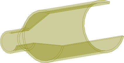
The present example considers a dual-mode axisymmetrical horn antenna (N.Farahat, W.Yu, R.Mittra, "A fast near-to-far transformation in body of revolution finite-difference time-domain method", IEEE Trans. Antenna Propagat., vol. 51, no. 9, pp. 2534-2540, Sept.2003).
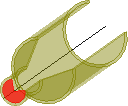
Dual-mode axisymmetrical horn antenna (V2D BOR).
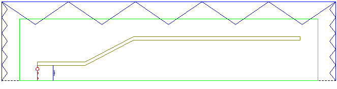
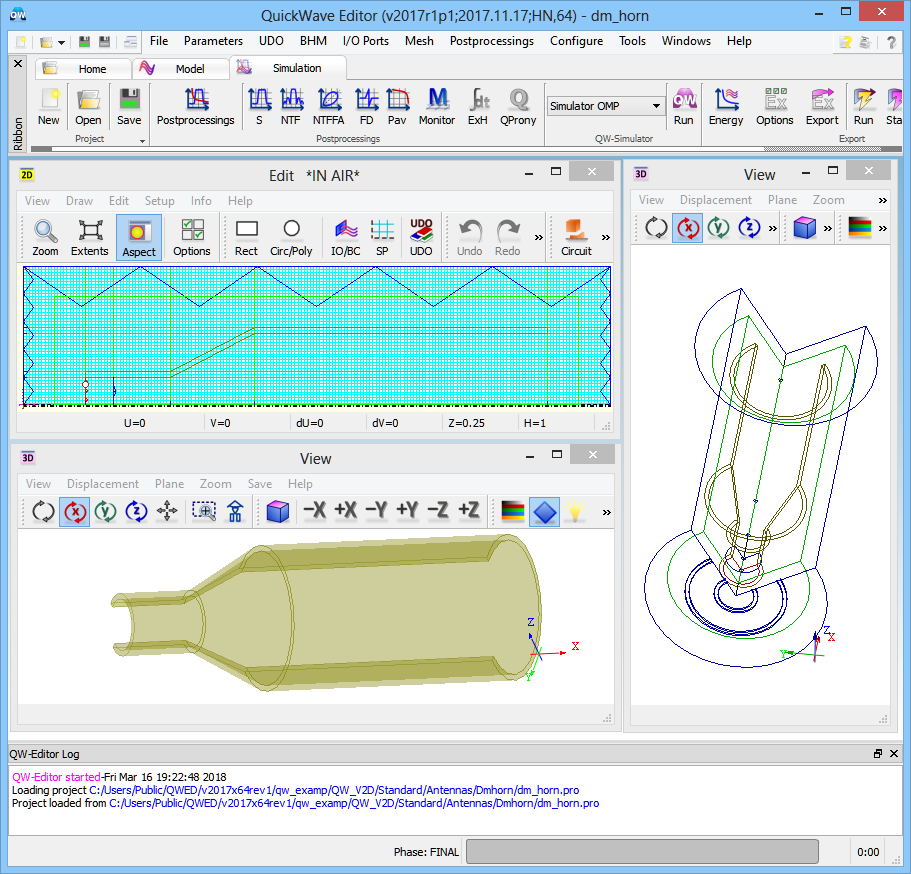
The structure that is analysed herein is an axisymmetrical horn antenna. Axial symmetry allows for performing the antenna analysis with ultra-fast vector 2D Bessel and FDTD hybrid solver (V2D BOR) designated for Bodies of Revolution (BOR) structures. This solver allows for analysing only half of structure's long-section, which results in its extremely fast performance. The structure should be drawn in a way that its symmetry axis coincides with project symmetry axis ρ=0 (in the QW-Editor and QW-Simulator referred as y=0).
Dual-mode axisymmetrical horn antenna (V2D BOR) project in QW-Editor.
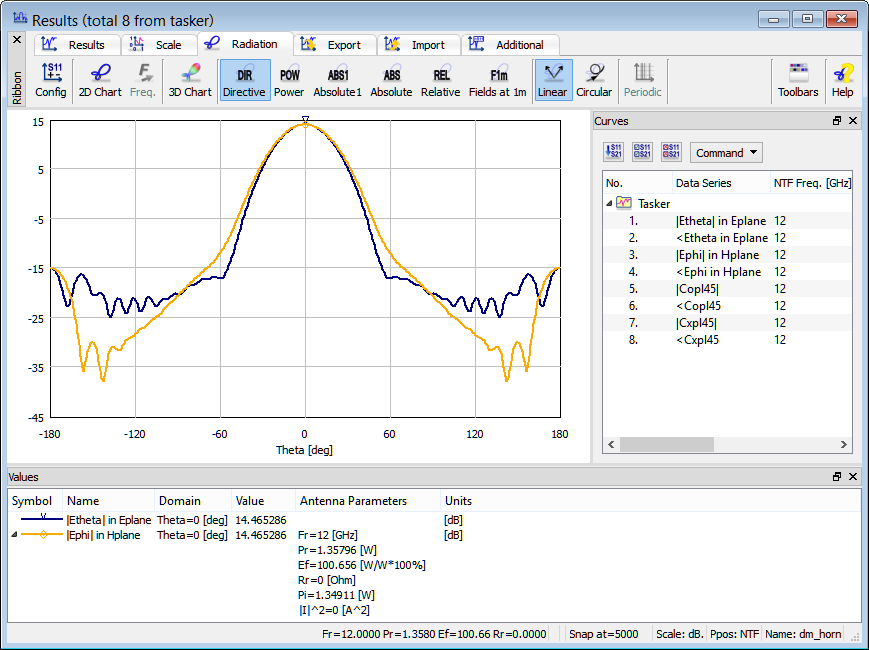
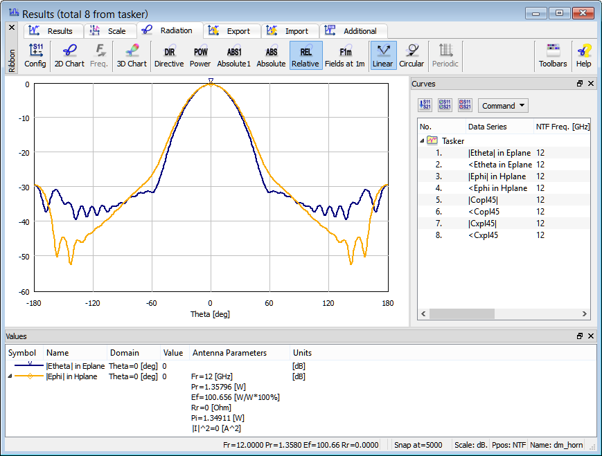
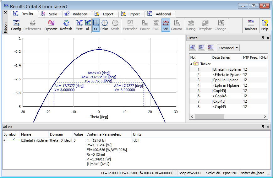
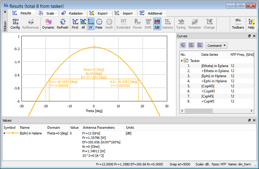
The green box visible in the simulation model is NTF Box, which is a virtual box determining the boundaries at which the near-to-far field transformation will be executed for the purpose of calculating the radiation patterns. In case of radiating scenarios, the entire project should be terminated with absorbing boundary conditions to model the free space surrounding. In this case we will use MUR absorbing boundary conditions in a form of MUR Box (blue box). The antenna is excited with the fundamental mode TE11 mode within a 10 GHz ÷ 14 GHz spectrum range. However, as the wave propagates through the tapered section, some of its energy is transformed into TM11 mode. Thus, an appropriate design allows us to equalise polarisation in E and H planes. It makes this horn a good feed for reflector antennas. Additionally, proper choices of flare angle and length of the horn’s tube help suppress the side lobes in the radiation pattern. Gain of this antenna is about 14.5 dB for both E and H planes. The 3 dB beamwidth is 35.5 degrees and 37.1 degrees for the E and H plane, respectively. Switching to Relative gain scaling shows that the side lobes are at the level of -30 dB.
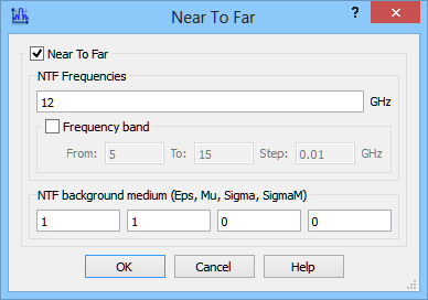
The radiation pattern calculations is set at 12 GHz.
Near To Far postprocessing configuration dialogue.
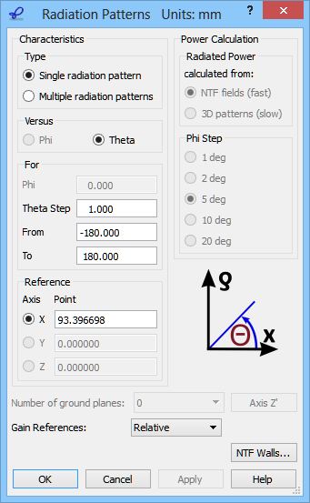
We wish to calculate the 2D radiation patterns versus angle Theta varying between -180 and 180 degrees with a step of 1 degrees. The definition of the angles is explained in the lower right part of the 2D Radiation Patterns configuration dialogue.
2D Radiation Patterns configuration dialogue.
2D radiation patterns calculated at 12 GHz for Directive gain.
2D radiation patterns calculated at 12 GHz for Relative gain.
The 3 dB beamwidth is 35.5 degrees for the E plane.
The 3 dB beamwidth is 37.1 degrees for the H plane.
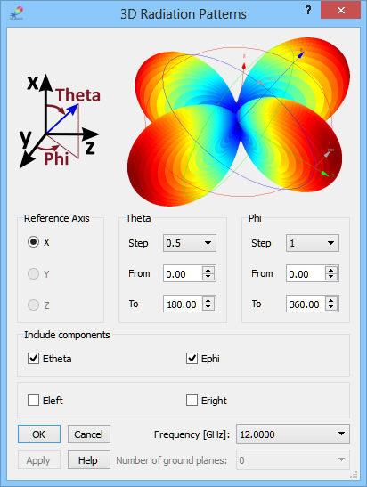
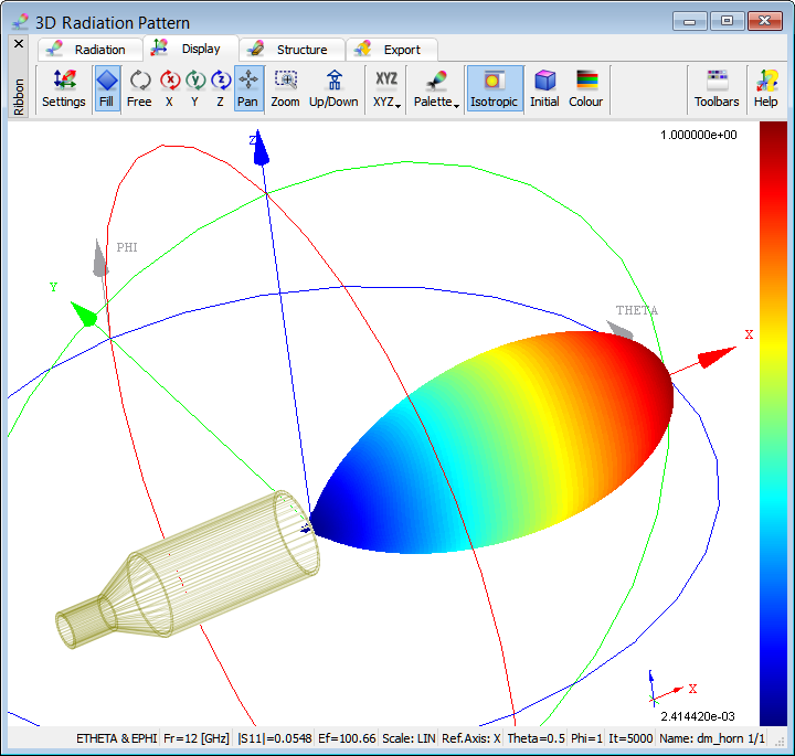
3D radiation pattern, with both Phi and Theta varying in steps, can be calculated in the 3D Radiation Pattern window. The 3D Radiation Patterns dialogue allows setting the reference axis and steps for angles Phi and Theta, defined with respect to that axis in the same way as for the 2D radiation pattern case. A single calculation frequency is also selected.