X-band magic T coupler
The present example considers X-band magic T coupler.
X-band magic T coupler.
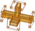
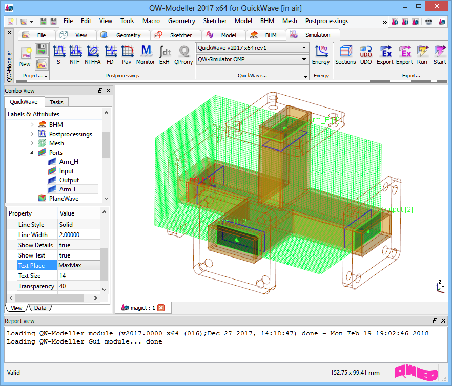
X-band magic T coupler project in QW-Modeller.
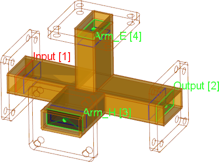
The structure is a model of X-band magic T (or magic tee or hybrid tee) waveguide coupler without matching elements (empty inside). The magic T consists of four rectangular waveguides (WR90 22.86 x 10.16 mm) meeting in a single junction. The ports are located inside the arms, behind the flanges. The FDTD mesh is limited to active areas only (flanges are not included) to make scenario as compact as possible.

The ports for S-parameters extraction are numbered as follows:
[1] - Input port
[2] - Output port
[3] - Arm H port
[4] - Arm E port

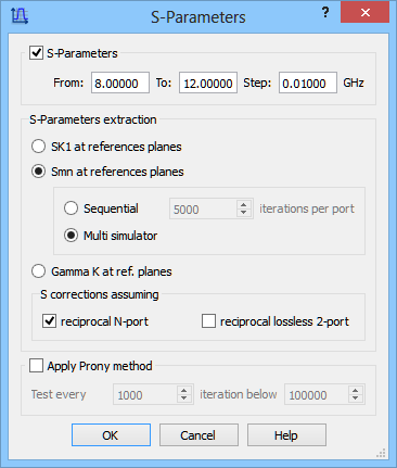
The S-Parameters postprocessing is set from 8 GHz to 12 GHz with the frequency step of 0.01 GHz.
The postprocessing will calculate full S-matrix (Smn option). It will be calculated in Multi simulator regime, which calculates all the matrix parameters simultaneously.
S-Parameters postprocessing configuration dialogue.
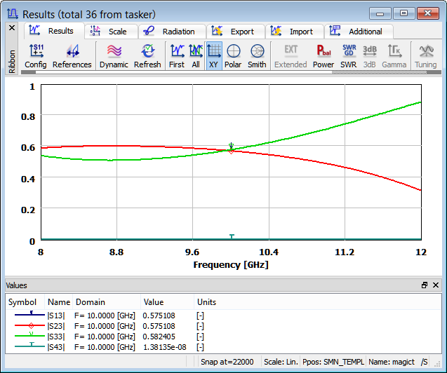
S-parameters results for excitation from arm H port [3]. Signal is divided equally between port [1] and port [2]. Port [4] is isolated.
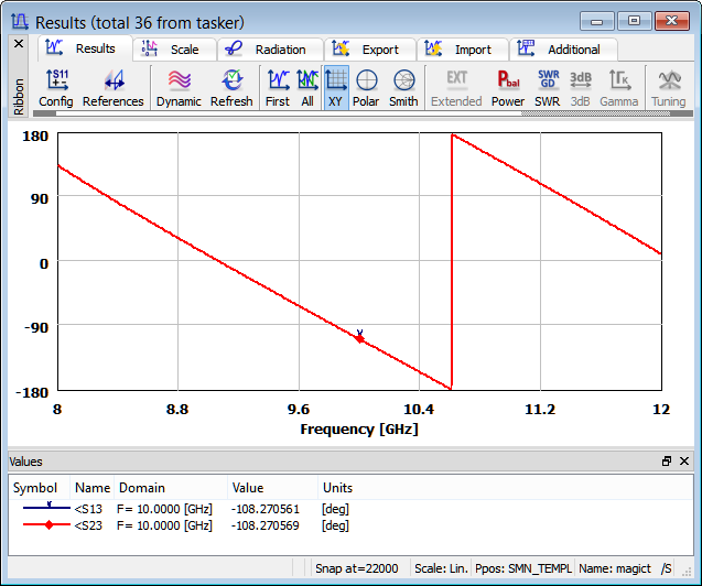
S-parameters results for excitation from arm H port [3]. Signal is in phase between port [1] and port [2].
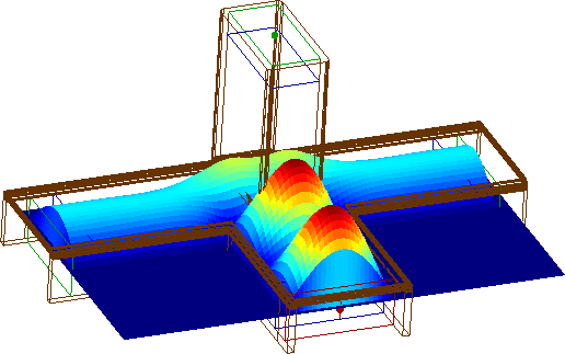
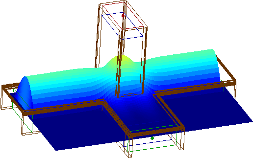
Envelope distribution of Ez field component at 10GHz, with excitation from from arm H port [3]. Signal is divided equally between port [1] and port [2]. Port [4] is isolated.
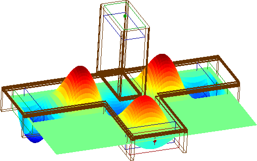
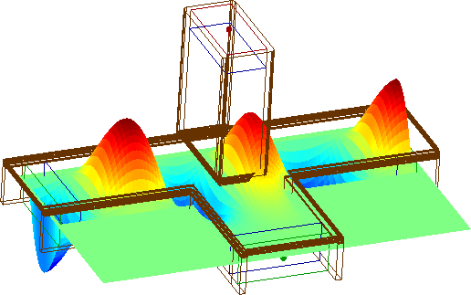
Ez field component distribution at 10 GHz, with excitation from arm H port [3]. Signal is in phase between port [1] and port [2].
Envelope distribution of Ez field component at 10GHz, with excitation from arm H port [3]. Signal is divided equally between port [1] and port [2]. Port [4] is isolated.
Envelope distribution of Ez field component at 10GHz, with excitation from arm H port [3]. Port [4] is isolated.
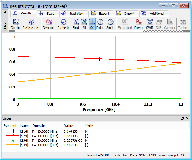
S-parameters results for excitation from arm E port [4]. Signal is divided equally between port [1] and port [2]. Port [3] is isolated.
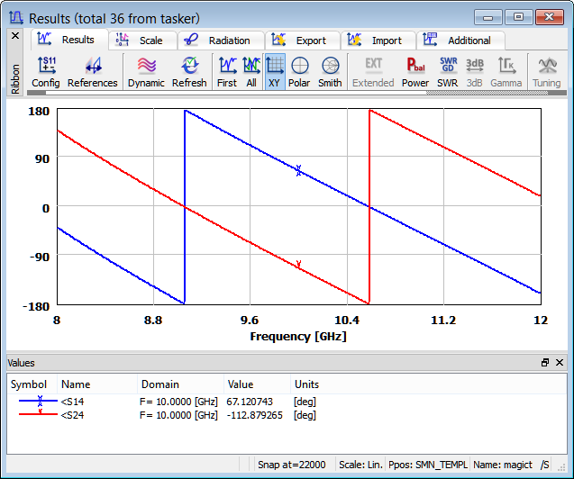
S-parameters results for excitation from arm E port [4]. Signal is 180o out of phase between port [1] and port [2].
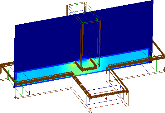
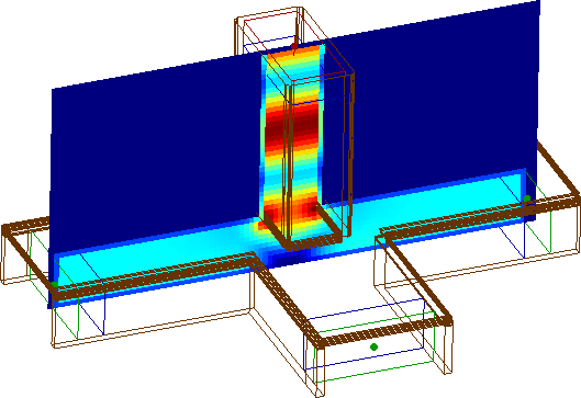
Envelope distribution of E field component at 10GHz, with excitation from arm E port [4]. Signal is divided equally between port [1] and port [2]. Port [3] is isolated.
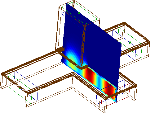
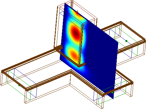
Ez field component distribution at 10 GHz, with excitation from arm E port [4]. Signal is 180o out of phase between port [1] and port [2].
Envelope distribution of E field component at 10GHz, with excitation from arm E port [4]. Signal is divided equally between port [1] and port [2]. Port [3] is isolated.
Envelope distribution of E field component at 10GHz, with excitation from arm E port [4]. Port [3] is isolated.
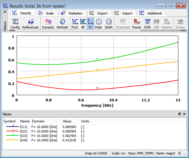
Return loss for all ports.