Parallel plate transmission line partially filled with concrete material
The present example considers a parallel plate transmission line partially filled with concrete material.
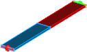
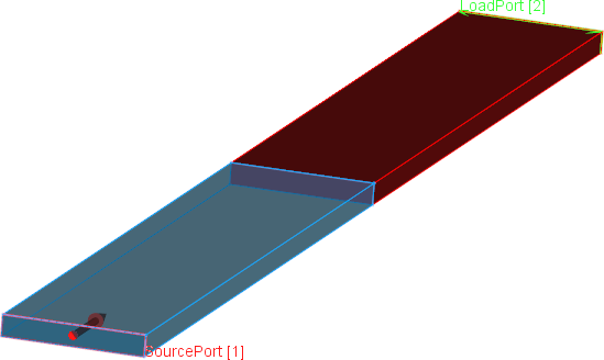
Parallel plate transmission line partially filled with concrete material.
Parallel plate transmission line partially filled with concrete material - violet colour on the both sides indicates PMC boundary conditions.
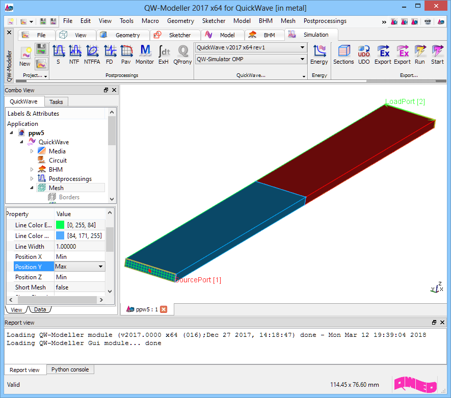
Parallel plate transmission line partially filled with concrete material project in QW-Modeller.
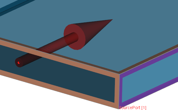
Simulation model presents parallel plate transmission line excited with a plane wave (red transmission line port) and terminated with a load port (green transmission line port) matched to the line. The transmission line is partially filled with air and concrete material with relative permittivity equal to 4.5.
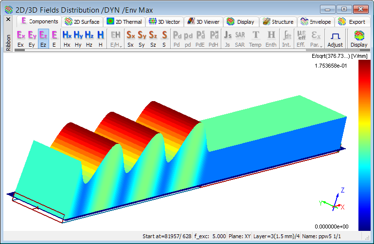
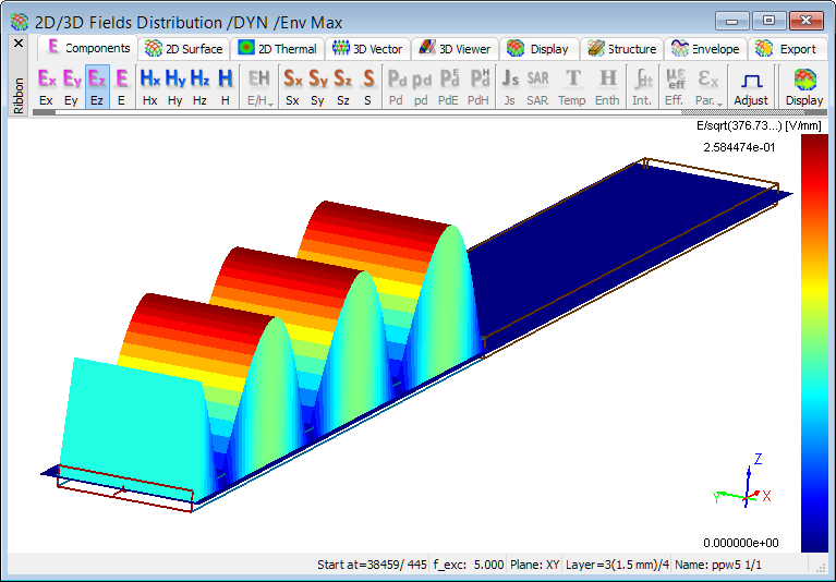
Distribution of time-maximum envelope of Ez field component at 5GHz.
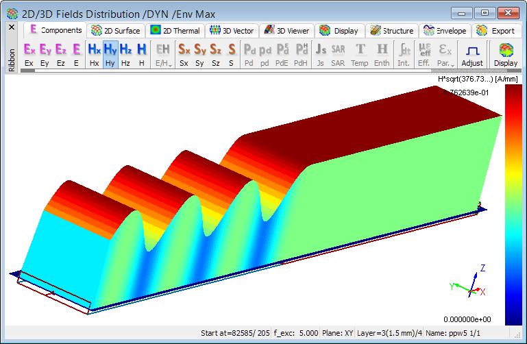
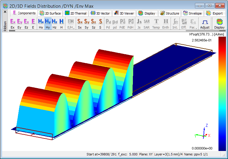
Distribution of time-maximum envelope of Hy field component at 5GHz.
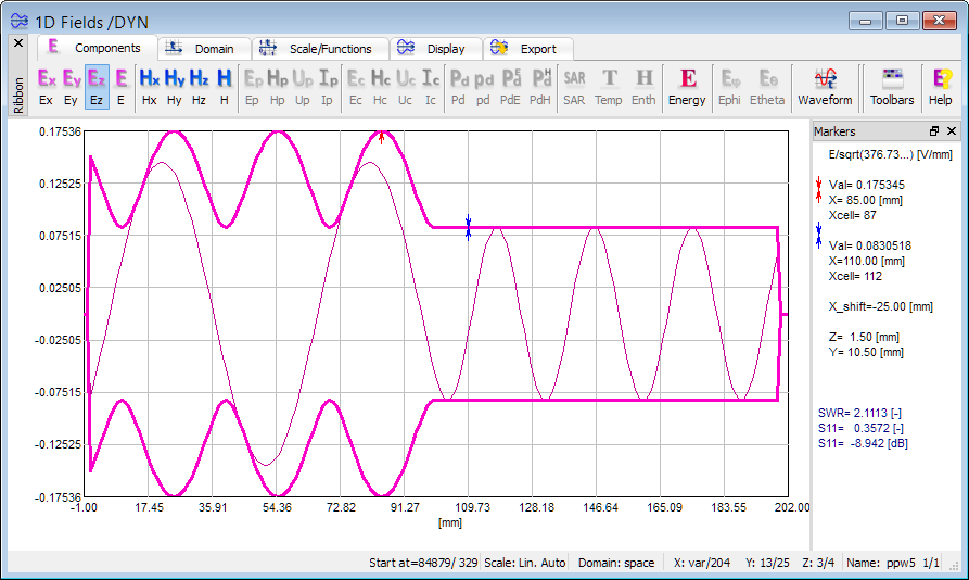
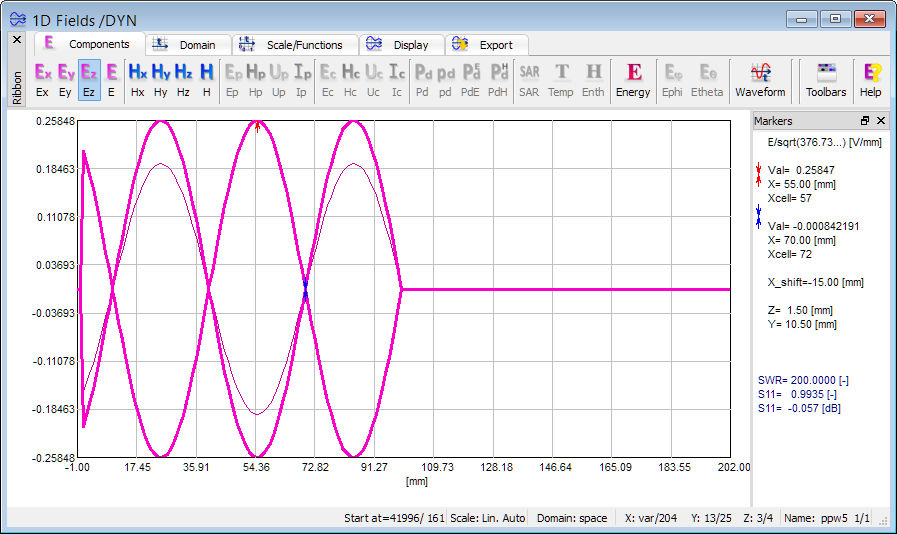
1D view of Ez field component distribution at 5GHz (instantaneous and envelope values).
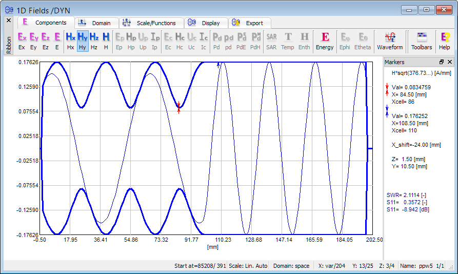
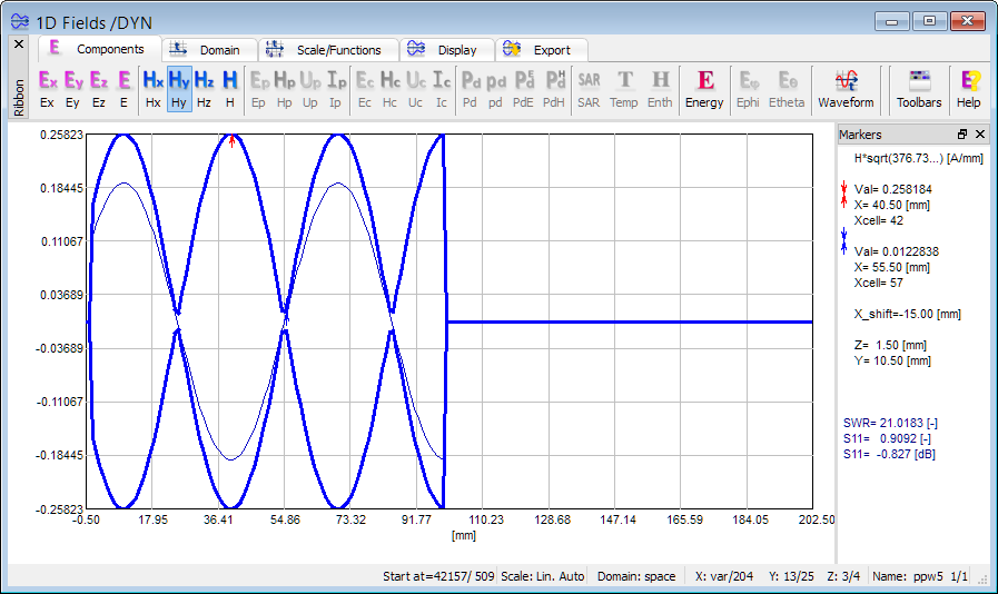
1D view of Hy field component distribution at 5GHz (instantaneous and envelope values).
The above displays prove that a wave propagating in parallel plate line reflects partially towards the source when reaches the concrete material surface and the rest propagates undisturbed in the concrete material towards matched output port. In the first part of the parallel plate line filled with air a partially standing wave can be easily observed.
Perfect electric conductor surface
In the second case, simulation model considers parallel plate line partially filled with air and PEC material.
Distribution of time-maximum envelope of Ez field component at 5GHz.
Distribution of time-maximum envelope of Hy field component at 5GHz.
1D view of Ez field component distribution at 5GHz (instantaneous and envelope values).
1D view of Hy field component distribution at 5GHz (instantaneous and envelope values).
The above displays show a total reflection from the PEC surface, resulting in a standing wave in an air filled part of the transmission line. The standing wave ratio (SWR) can be easily calculated (manually or automatically by choosing appropriate function from the menu) by placing markers at the maximum and minimum of electric field envelope.