Multi-conductor transmission lines
The present example considers multi-conductor transmission lines.
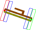
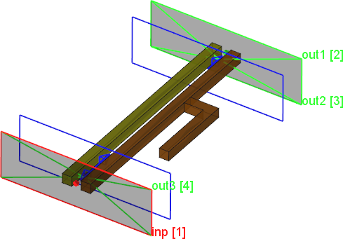
Multi-conductor transmission lines.
Simulation model considers a pair of coupled strip-lines, shielded with the ground plane on all sides. The inner conductor of one of the coupled lines is a straight one and built of material metal1. The inner conductor of the other line is straight but with a G -shape stub connected to it, and it is built of material metal2. The ground planes are made of the material metal.
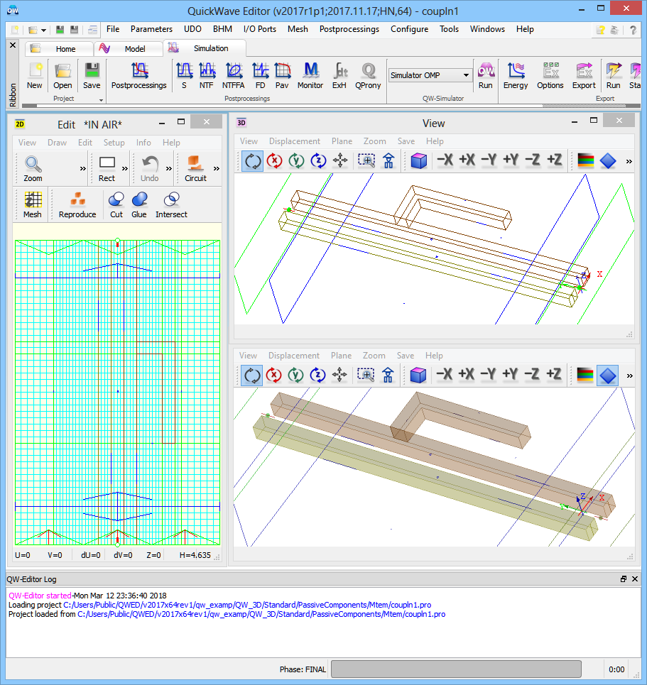
Multi-conductor transmission lines project in QW-Editor.
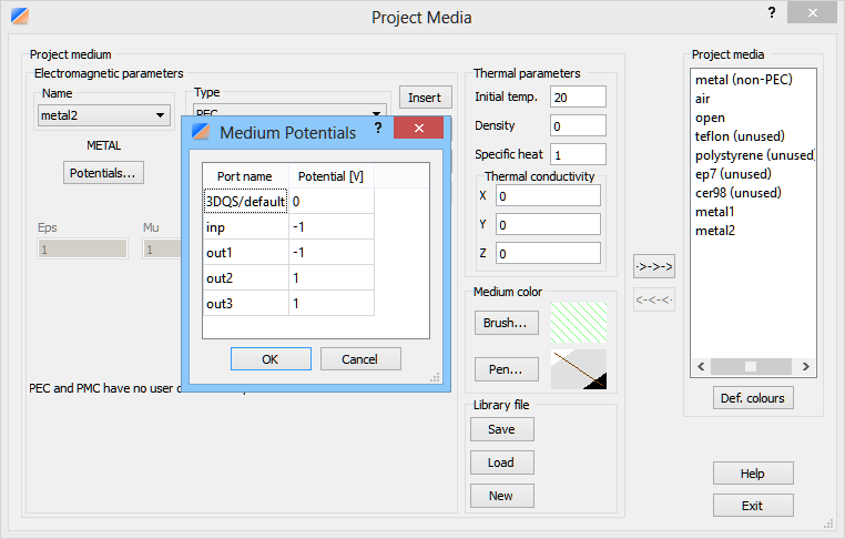
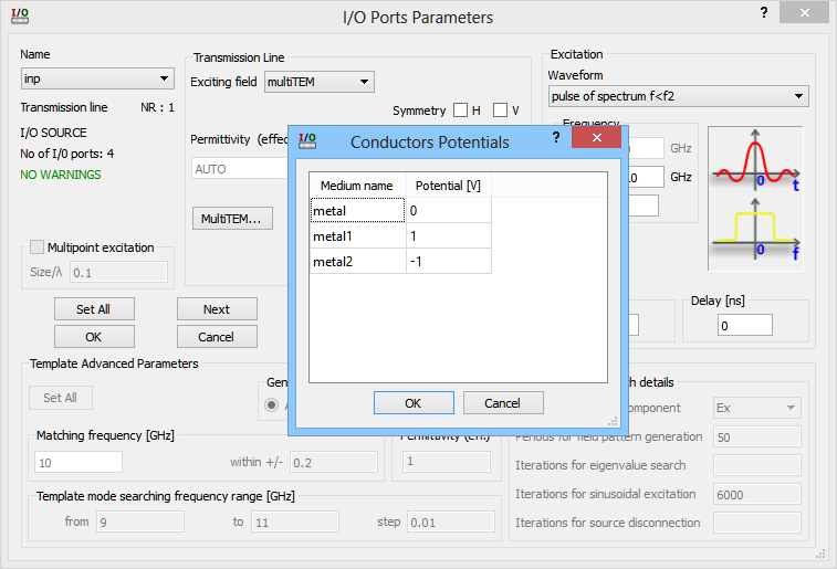
In the four ports existing in the project, the value in the four ports already existing in the projects the value of the potential for metal2 is -1 for ports inp and out1 and +1 for ports out2 and out3.
Potential assignment for medium metal2.
The potentials for metal2 in a particular port can be changed in the port dialogue. We can see that metal2 has in that port potential –1 (as noted previously) while metal has the potential 0 and metal1 – potential 1.
Potential assignment for port inp.
Review of all other ports settings reveals that in the considered project we have assigned the following modes to the particular ports:
•
to port No.1 inp we have assigned an odd mode (with potentials 1 and –1 on the two conductors of the coupled pair),
•
to port No.2 out1 we have assigned an odd mode,
•
to port No.3 out2 we have assigned an even mode (with potentials equal 1 on both conductors of the coupled pair),
•
to port No.4 out3 we have assigned an even mode.
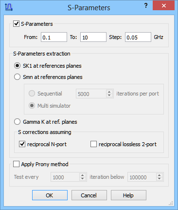
For the purpose of calculating reflection and transmission characteristics of the structure the S-Parameters postprocessing is activated. The S-Parameters postprocessing is set from 0.1 GHz to 10 GHz with a frequency step of 0.05 GHz.
S-Parameters postprocessing configuration dialogue.
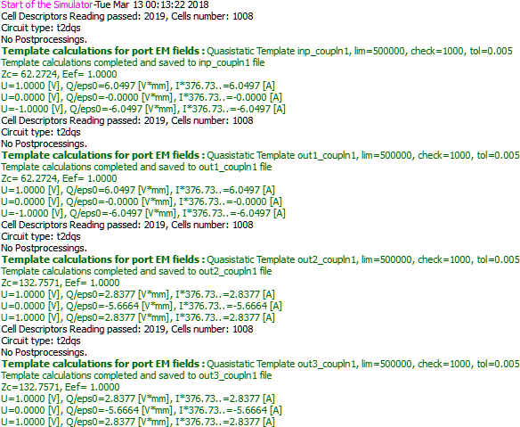
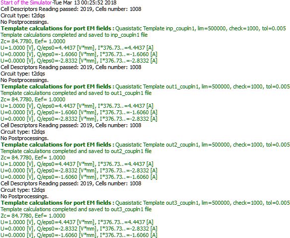
For a TEM template in a two-conductor line the presentation of the line impedance and effective permittivity is sufficient to characterise the line. To have full information about a multi-conductor line, we need to know the charge stored on each conductor and the current flowing in it under the conditions enforced by the particular distribution of voltages. Thus the Simulator Log presents this information with respect to each of the conductors. We have the voltage on it, the charge and the current. The units have been chosen in a way that charge and current are numerically equal in the case of an air-filled line. The considered port (inp) is defined on the odd mode (with voltages: +1,-1). Thus the detected impedance 62.27 W is the odd-mode impedance. For ports 3 and 4 we consider the even mode and thus the impedance 132.76 W detected there is the even-mode impedance.
Simulator Log window in QW-Simulator with a sequence of lines for multi TEM template calculations.
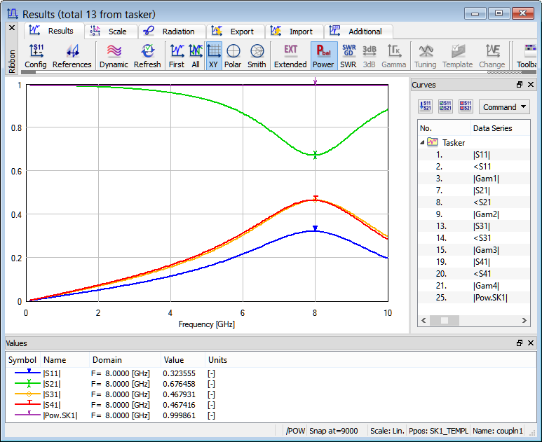
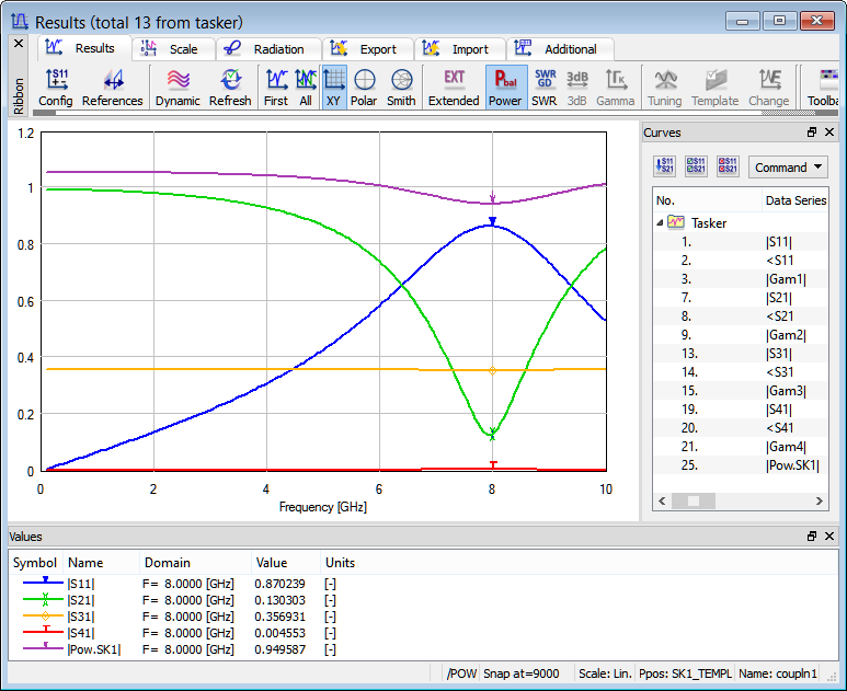
For low frequencies the two considered modes are decoupled. At 8 GHz the electrical length of the stub is close to half wavelengths. Thus one of the lines is close to being short-circuited and this causes a strong coupling between the odd and even modes. However, let us note that since the considered modes are orthogonal the power balance remains equal to 1 all over the frequency band.
S-Parameters characteristics.
Now we apply the following potentials on the conductors of the coupled pair of strip-lines:
•
to port No.1 inp potentials 0 and 1,
•
to port No.2 out1 potentials 0 and 1,
•
to port No.3 out2 potentials 1 and 0,
•
to port No.4 out3 potentials 1 and 0.
Simulator Log window in QW-Simulator with a sequence of lines for multi TEM template calculations with modified settings.
It is interesting to note that the mode with voltages 0,1 and the mode with voltages 1,0 are not mutually orthogonal. That is why in the results of simulation we can find that the calculated power balance deviates from unity.
S-Parameters characteristics.